Lesson 7/1070%
MODULE 07

Surge Protection Components

No single component protects against every surge -- each device trades off response speed, energy capability, leakage current, and capacitance differently, which is exactly why real designs combine several of them.
Learning Objectives

🧩
Understand the working principle of every major protection component
⚖️
Compare response time, energy capability, leakage & capacitance
🔗
Understand why components are combined into staged protection
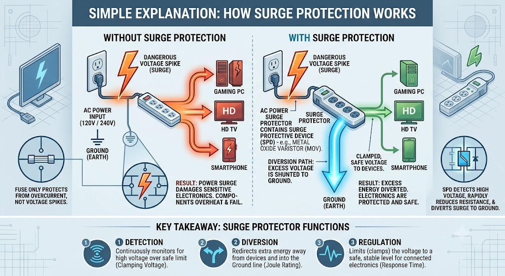
Simple diagram comparing an unprotected outlet, where a voltage spike damages a gaming PC, TV and smartphone, against a protected outlet with a surge protector that detects, diverts and regulates the spike safely to ground
Before the component-level detail below: every protection device in this section exists to do one of three jobs -- detect an overvoltage, divert the excess energy to ground, and regulate (clamp) the remaining voltage to a safe level for connected electronics.

🔊 Audio Explanation: Section 1

Prefer to listen? Press play for a full narrated walkthrough of every protection component in this section before (or instead of) exploring the cards yourself below.

Ready to play · about 3 minutes

Show full transcript
Component Response Time Energy Capability Leakage Current Capacitance Relative Cost

Response Time vs. Energy Capability (Illustrative, log scale)

A GDT alone is too slow to protect a sensitive IC -- by the time it ionizes and clamps, several hundred volts may already have reached the load. A TVS diode alone is too small to absorb a full lightning-induced surge. Staging a slower, high-energy device upstream with a faster, lower-energy device downstream -- separated by a decoupling impedance -- lets each component do the job it is best suited for.
🔊 Audio Explanation: Section 3

Press play for a detailed narrated walkthrough of staged protection: what each stage does, why the decoupling impedance between them is the real trick, and how the animation below maps onto a real circuit board.

Ready to play · about 3 minutes

Show full transcript
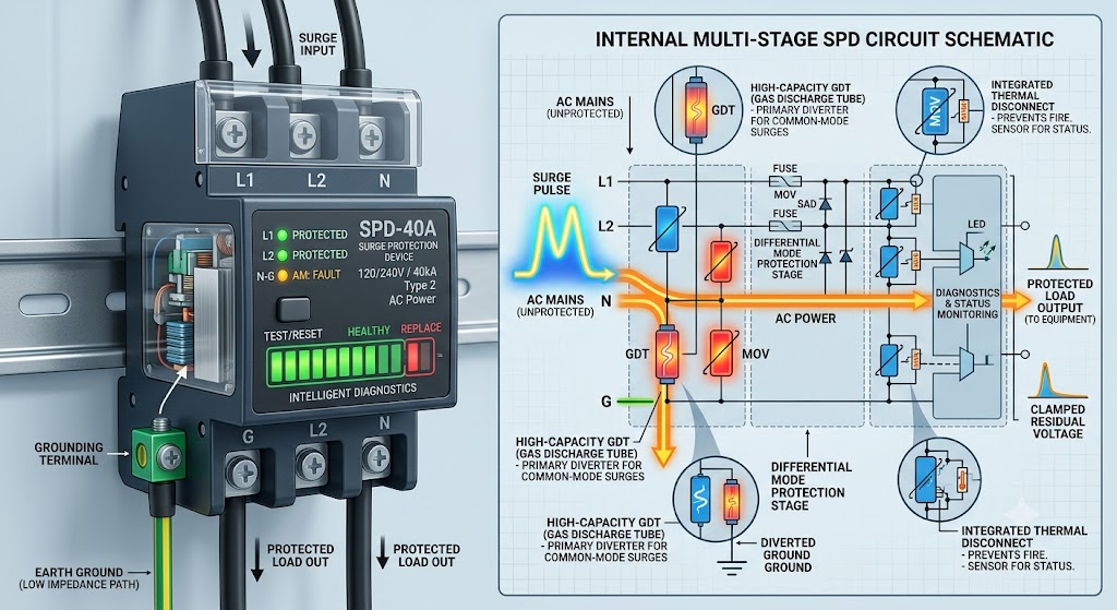
Real multi-stage SPD device and its internal circuit schematic, showing a high-capacity GDT as the primary common-mode diverter, a differential-mode MOV/SAD protection stage, fuses, an integrated thermal disconnect, and diagnostics/status monitoring feeding a protected load output
A real commercial SPD (left) and its internal multi-stage circuit (right): a high-capacity GDT diverts the bulk of common-mode surge current to ground, a downstream MOV/SAD stage handles differential-mode protection, fuses and a thermal disconnect guard against follow-on current and overheating, and onboard diagnostics report device health -- the same staged philosophy animated below.

Stage 1 (GDT) diverts the bulk of the surge current to ground but clamps relatively loosely and slowly. The decoupling inductor/impedance forces enough voltage across itself during the GDT's turn-on delay to keep the downstream voltage from exceeding Stage 2's rating. Stage 2 (TVS) then cleans up the remaining, faster-rising residual voltage down to a level safe for the protected IC.

The Same Stages on a Real Circuit & Board

What the animation abstracts, a real design implements: the schematic (left) is the staged circuit, and the board view (right) shows where each part physically sits — the GDT at the cable entry with a short, wide earth path, and the TVS at the far end, next to the pin it protects. The trace length between them is part of the decoupling impedance.

Schematic
STAGE 1: GDT DECOUPLING STAGE 2: TVS Line in (surge) GDT L (or R) decoupling TVS Protected IC PE / GND
Board placement (top view)
ENTRY / STAGE 1 DECOUPLING STAGE 2 + LOAD cable entry GDT chassis earth lug short, wide strap L1 trace length adds to decoupling TVS via array to GND Protected IC TVS a few mm from the pin
Voltage coordination between stages must be verified during design -- if the let-through voltage of Stage 1 exceeds Stage 2's maximum rating before the decoupling impedance limits it, Stage 2 can be destroyed before Stage 1 ever activates.
KNOWLEDGE CHECK

Module 7 Quiz

Score: 0 / 12

Select the best answer for each question. Instant feedback is provided after each response.

Question 1 of 12