Lesson 5/1050%
MODULE 05
Test Setup, CDN & Coupling Methods
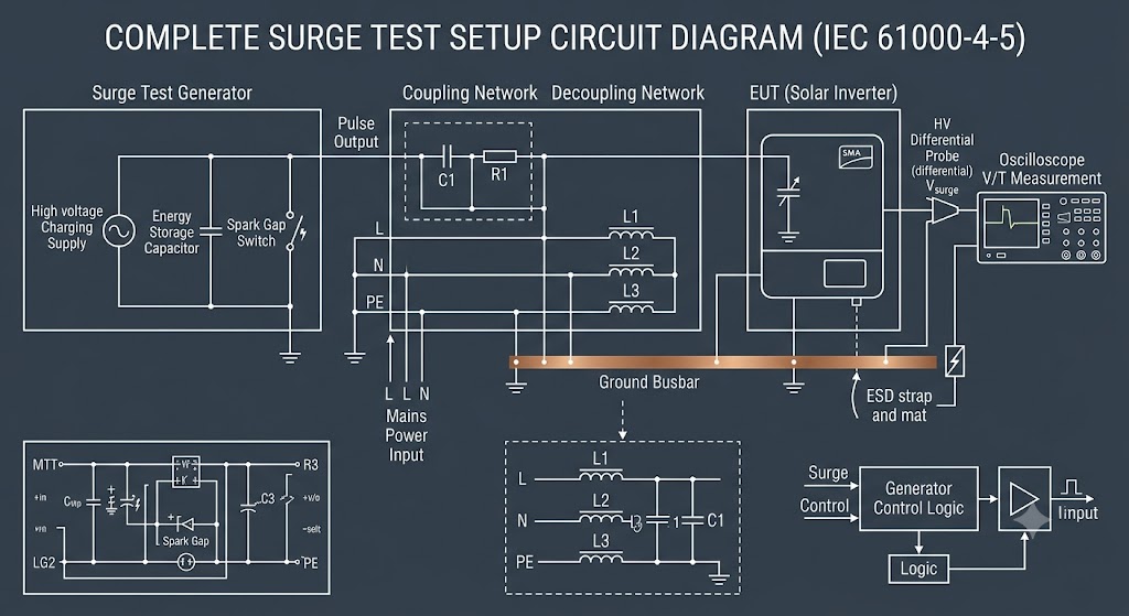
A surge test bench looks deceptively simple -- a generator, a box, some cables -- but every component exists to force the surge energy down one specific, repeatable path into the equipment under test.
Click each component below to see its purpose, the physics behind it, and the common variants used in real test labs.
| Aspect | Common-Mode | Differential-Mode |
|---|---|---|
| Current path | Both conductors to ground/earth, in phase | Out and back between two conductors |
| Typical source | Lightning-induced ground potential rise, indirect strikes | Switching transients, direct line coupling |
| Protection component | GDT or MOV line-to-ground | MOV or TVS line-to-line |
| Relative real-world frequency | More common on outdoor / long cable runs | More common indoors, closer to the switching source |
KNOWLEDGE CHECK
Module 5 Quiz
Score: 0 /
12
Select the best answer for each question. Instant feedback is provided after each response.
Question 1 of
12