ESD Generator, Test Setup & Current Waveform
The ESD gun, the coupling planes it discharges through, and the exact shape of the current pulse it injects are all tightly specified by IEC 61000-4-2 -- understanding each piece is what makes a lab report readable and a design decision defensible.
Click each part of the generator below to see what it does.
Two indirect-discharge coupling planes let the standard reproduce nearby discharges without touching the EUT directly, simulating a spark near (not necessarily on) the product.
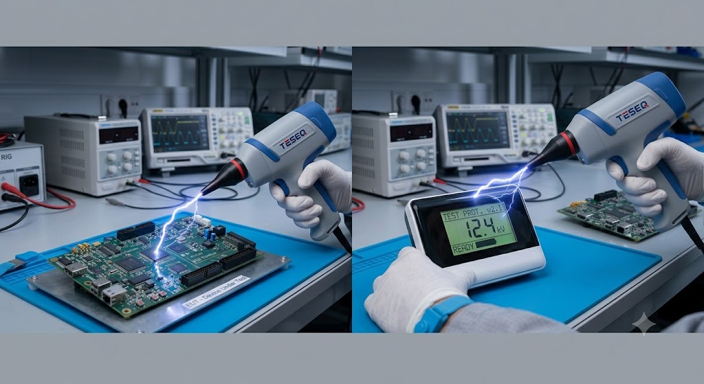
A compliant ESD test bench is more than just the gun -- every piece pictured in a typical IEC 61000-4-2 tabletop setup has a defined purpose, a physics reason for existing, and often more than one real-world variant. Select a component below for a detailed illustrated breakdown.
| Component | Typical Spec | Key Physics Role |
|---|---|---|
| ESD Generator | 150 pF / 330 O network, up to 15-30 kV | Produces the standardized Ip/I30/I60 current waveform |
| Contact discharge tip | Sharp pointed metal tip | Direct, repeatable galvanic connection at the relay-defined instant |
| Air discharge tip | Rounded ball tip, larger radius | Controlled, if less repeatable, air-gap breakdown geometry |
| HCP | 1.6 m x 0.8 m metal sheet | Capacitive coupling path for indirect tabletop discharges |
| VCP | 0.5 m x 0.5 m metal sheet | Capacitive coupling path simulating a nearby person/object |
| Ground reference plane | Copper or galvanized steel, extends ≥0.5 m beyond EUT | Low-impedance common return reference for the whole setup |
| Insulating table | 0.8 m height, non-conductive | Standardizes the HCP-to-GRP stray capacitance geometry |
| Bleed resistors | 470 kO, two per coupling plane | Drain accumulated charge slowly without loading the fast transient |
| Ground/bonding strap | Short, wide braided copper | Minimizes inductance in the generator's HF return path |
IEC 61000-4-2 specifies the exact current waveform a compliant generator must produce, defined by three parameters: the first peak current Ip (reached in a 0.7-1 ns rise time), the current at 30 ns (I30), and the current at 60 ns (I60). Select a test level to see the specified values.
| Level | Test Voltage | Ip | I30 | I60 |
|---|---|---|---|---|
| 1 | 2 kV | 7.5 A | 4 A | 2 A |
| 2 | 4 kV | 15 A | 8 A | 4 A |
| 3 | 6 kV | 22.5 A | 12 A | 6 A |
| 4 | 8 kV | 30 A | 16 A | 8 A |
Module 5 Quiz
Select the best answer for each question. Instant feedback is provided after each response.