Introduction & What Are Radiated Emissions
Every electronic product generates electromagnetic energy during normal operation. If that energy escapes through cables, PCB traces, enclosures, or antennas into free space, it becomes Radiated Emissions (RE) — and virtually every EMC standard on earth requires you to measure and control it. This module builds the mental model you'll use for the rest of the course: what RE is, why it's a legal gate to market, and how a single clock frequency creates a whole family of emissions.
Every electronic product generates electromagnetic energy during its normal operation. If this energy escapes through cables, PCB traces, enclosures, or antennas into free space, it becomes Radiated Emissions (RE).
Radiated emissions are unwanted electromagnetic waves generated unintentionally by electronic circuits. These emissions may interfere with nearby electronic equipment, wireless communication systems, navigation systems, medical equipment, military electronics, and safety-critical devices.
EMI, EMC, and RE: How the Terms Relate
These three terms are often used loosely, but each means something specific. EMI (Electromagnetic Interference) is the disturbance itself — the unwanted energy that disrupts another device. EMC (Electromagnetic Compatibility) is the broader engineering discipline: designing a product so it neither causes EMI in others nor is disrupted by EMI from others. RE (Radiated Emissions) is one specific, measurable slice of EMC — the emissions half, measured through the air rather than through cables (conducted emissions) or against incoming disturbances (immunity/susceptibility).
Radiated emissions are electromagnetic waves unintentionally emitted into free space by an electronic product. Unlike conducted emissions that travel through power or signal cables, radiated emissions propagate through the air.
Example Sources
Worked Example: Harmonics
A microcontroller operating at 100 MHz produces harmonics at 200 MHz, 300 MHz, 400 MHz, 500 MHz, and so on. These harmonics radiate through power planes, signal traces, ground discontinuities, and cable harnesses — often at levels far above the fundamental once trace and cable resonances are factored in.
Animated: Harmonic Amplitude Falls With Frequency
In a real spectrum scan, the fundamental is usually the tallest peak, and each successive harmonic is progressively weaker — but a harmonic that lines up with a cable or trace resonance can spike well above its neighbors. Watch the bars settle into a realistic decaying pattern with one resonance-driven spike.
Near Field vs. Far Field
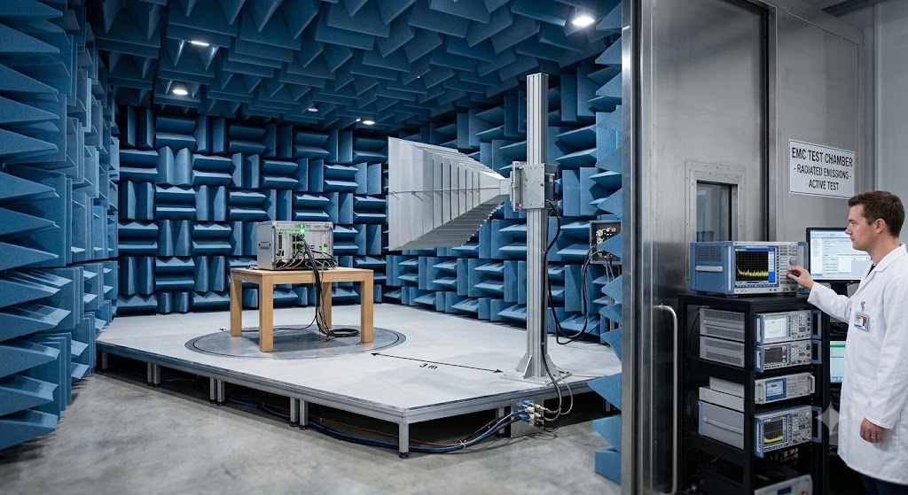
Close to the source (roughly within λ/2π of the emitter), the electric and magnetic field strengths behave independently and fall off very quickly with distance — this is the near field. Beyond that boundary, the fields lock together into a self-sustaining electromagnetic wave that falls off much more predictably with distance — the far field. Compliance testing is deliberately performed in the far field (hence the fixed 1 m, 3 m, or 10 m test distances you'll see in Modules 06–08) so that measurements are repeatable and comparable between labs.
Interactive: EM Wave Propagation
A radiated emission is, physically, a traveling electromagnetic wave. Press play to animate a simplified E-field waveform propagating away from the source — drag the frequency slider to see how a higher clock frequency compresses the wave into a shorter wavelength, exactly as in the frequency/wavelength table above.
Interactive: Second Worked Example — 133 MHz Clock
Not every clock is a round number like 100 MHz. Many real processors and memory buses run at frequencies such as 133 MHz, 166 MHz, or 400 MHz. Hover the bars below to see exactly where each harmonic of a 133 MHz clock falls — useful practice for reading a real spectrum analyzer trace in Module 08.
Module 1 Quiz
Select the best answer for each question. Instant feedback is provided after each response.